
Fast-Stat Installation Instructions
The Simple thermostat requires a C-wire connection for continuous power in order to maintain Wi-Fi connectivity. Some houses have a C-wire already at the thermostat, but if not you will need to use either a Fast-Stat 1000, or a Fast-Stat Common Maker, depending on your household wiring. Common configurations found in houses that are covered in this guide are:
- 4 Wire Heating and Cooling - Rh/Rc, W, Y, G - This requires the Fast-Stat 1000
- 3 Wire A/C only - Rh/Rc, Y, G - This requires the Fast-Stat 1000
- 2 Wire Heating only - Rh/Rc, W - This requires the Fast-Stat Common Maker
Not sure about your wiring? Please visit http://www.thesimple.com/compatibility for more information.
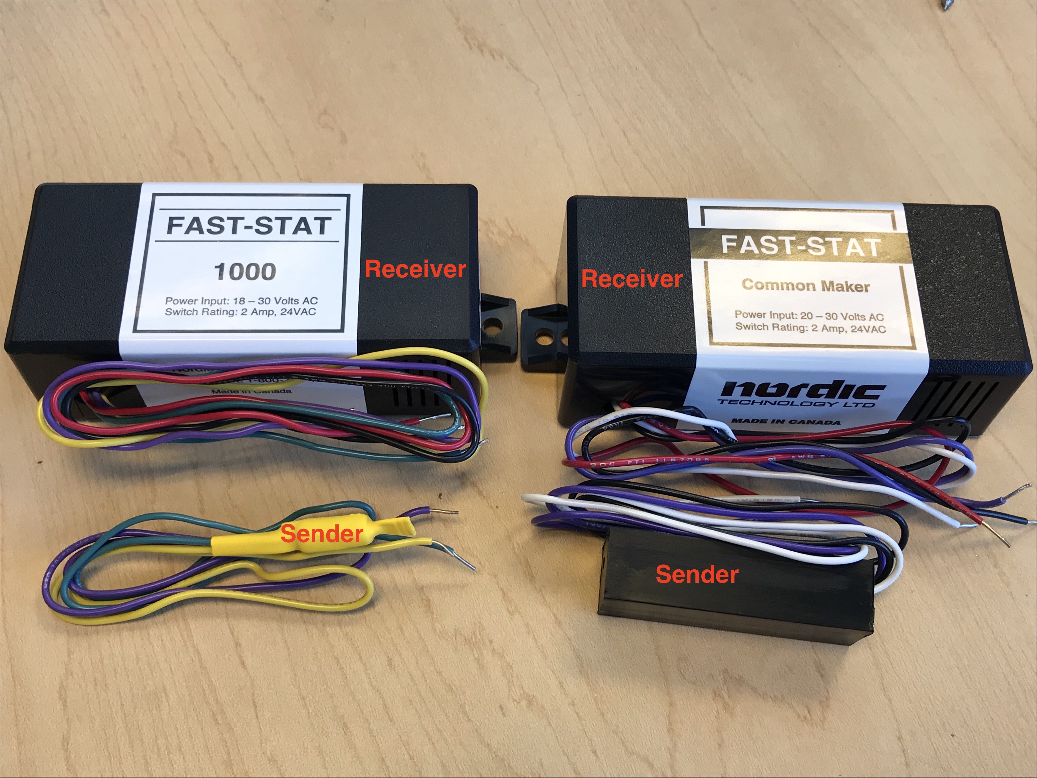
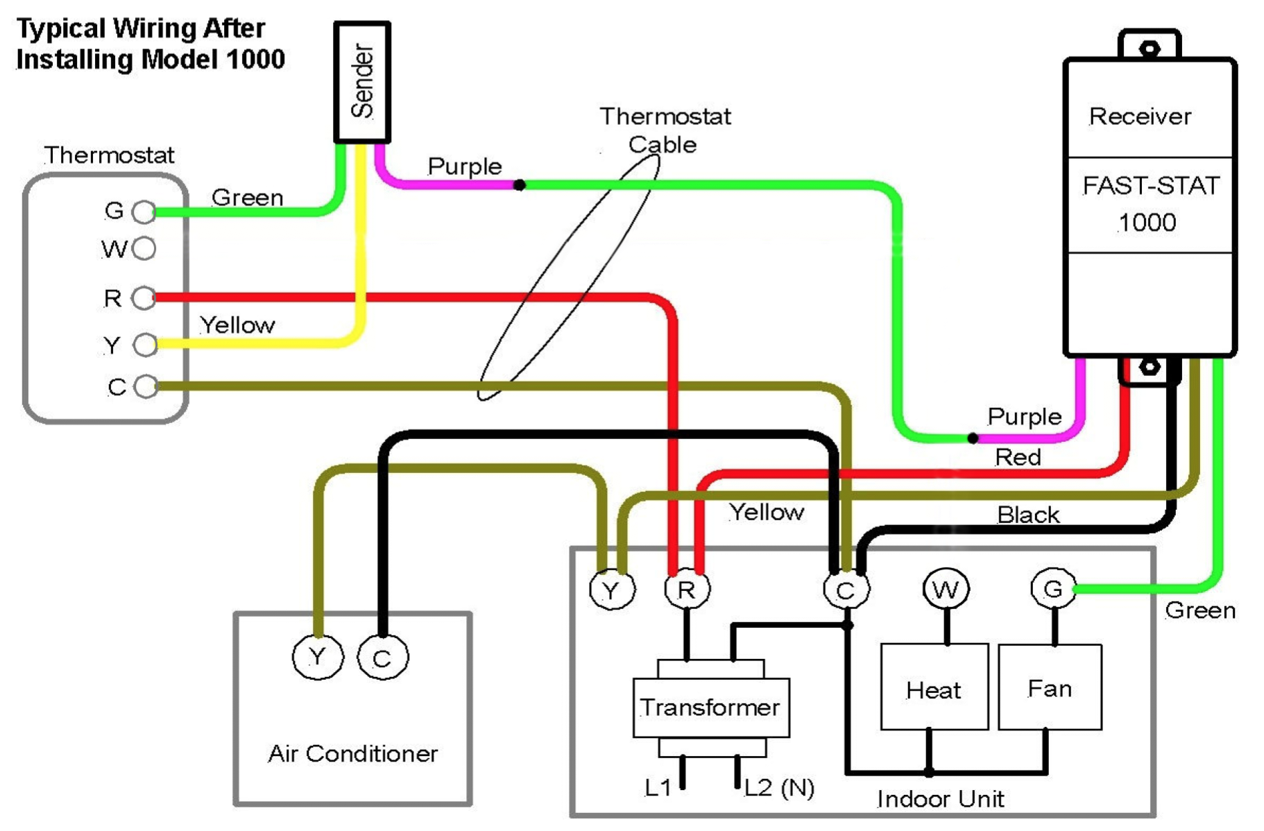
Both the Fast-Stat 1000 and the Fast-Stat Common Maker come with a receiver (top) and a sender (bottom). The receiver gets mounted next to your A/C control panel, and the sender goes behind your thermostat, tucked into the wall.
To perform the installation you will need a small phillips screwdriver, a set of wire strippers/cutters, and the supplied wire nuts.
4 Wire - A/C and Heating with Fan Control with the Fast-Stat 1000
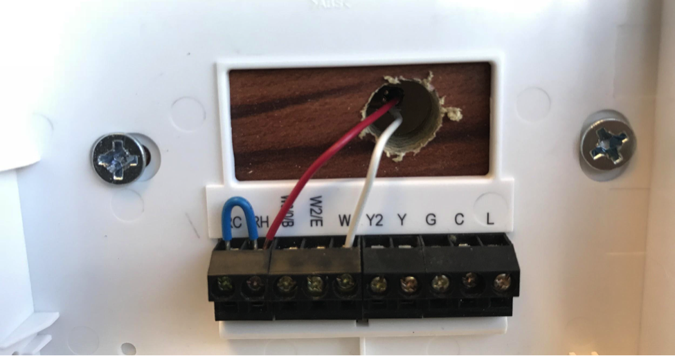
At the thermostat:
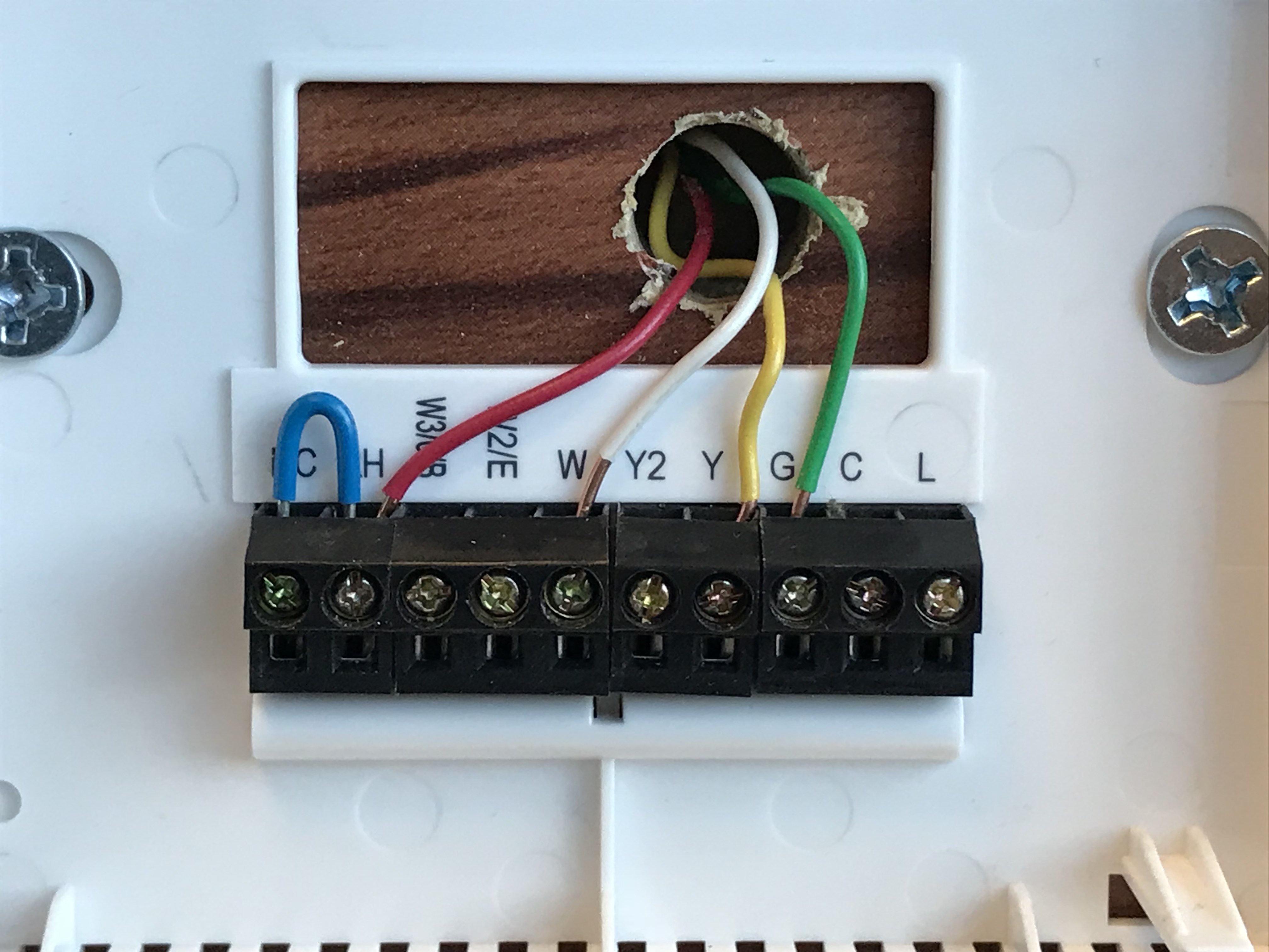
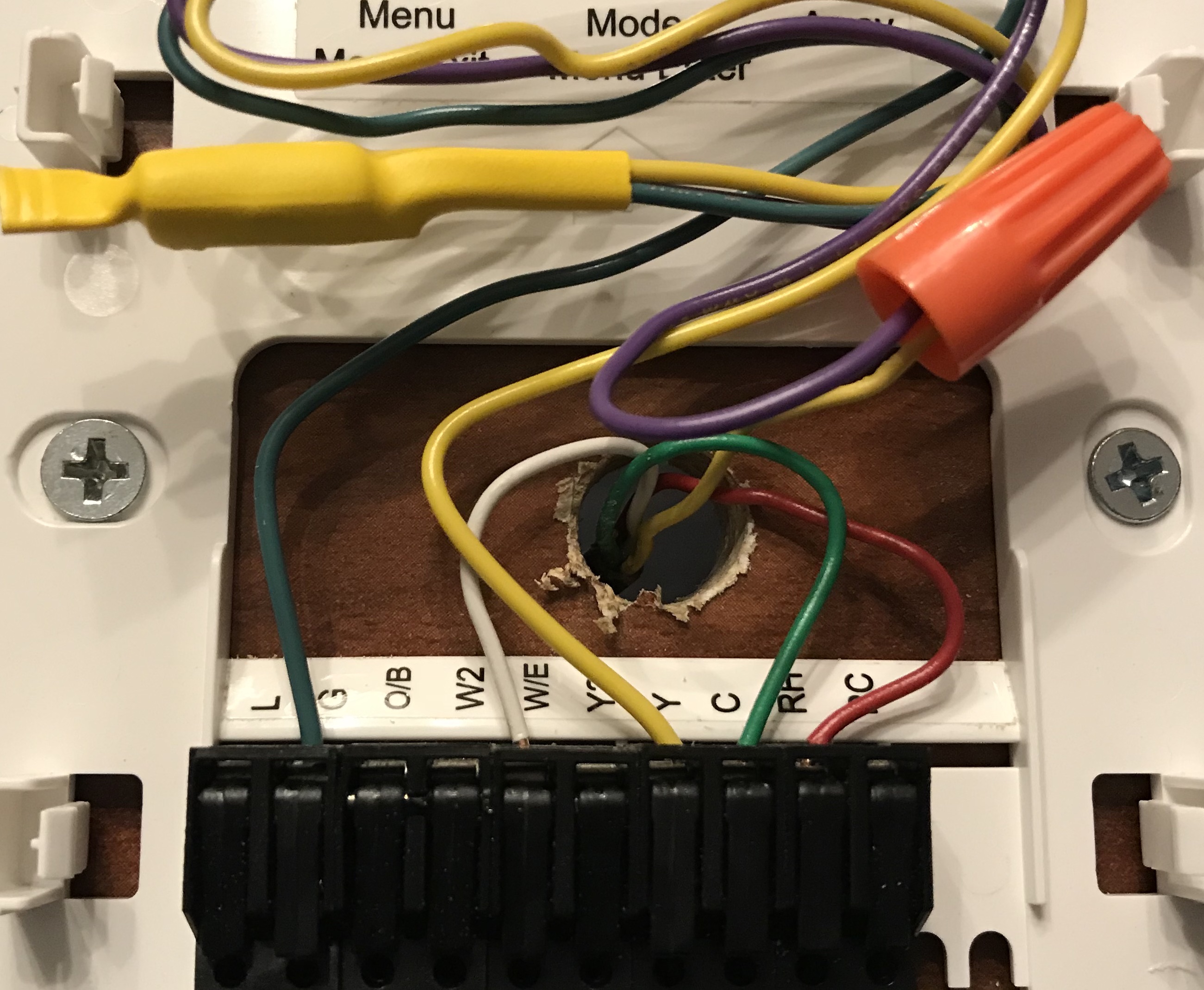
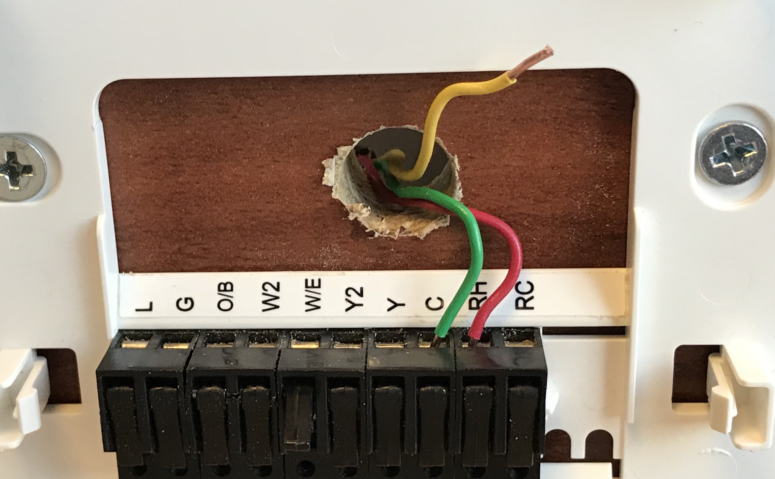
Shut off the power to your thermostat and remove it from the wall. You should see a wiring setup that looks similar to the image below. Take a picture of this wiring to use as reference.
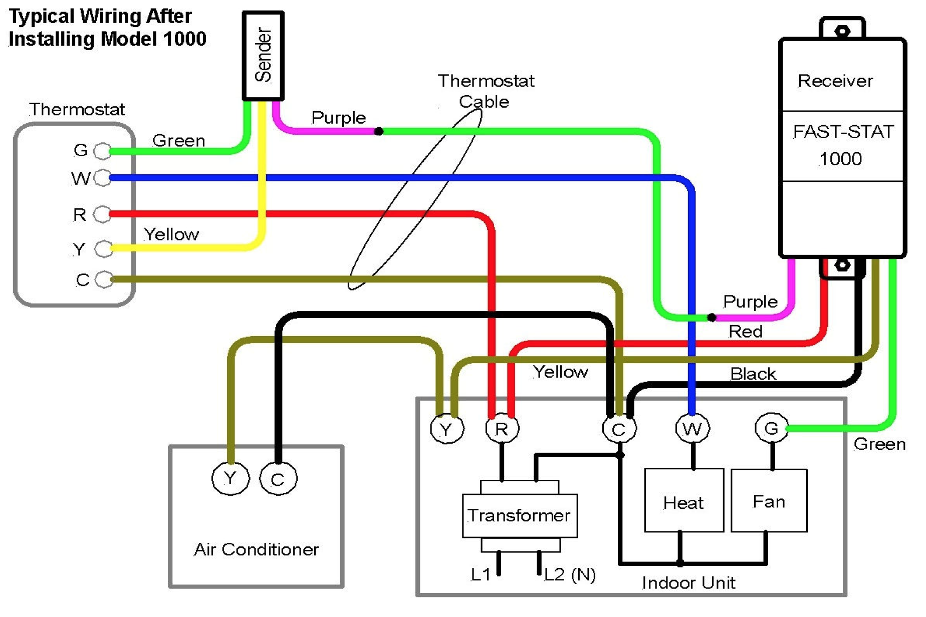
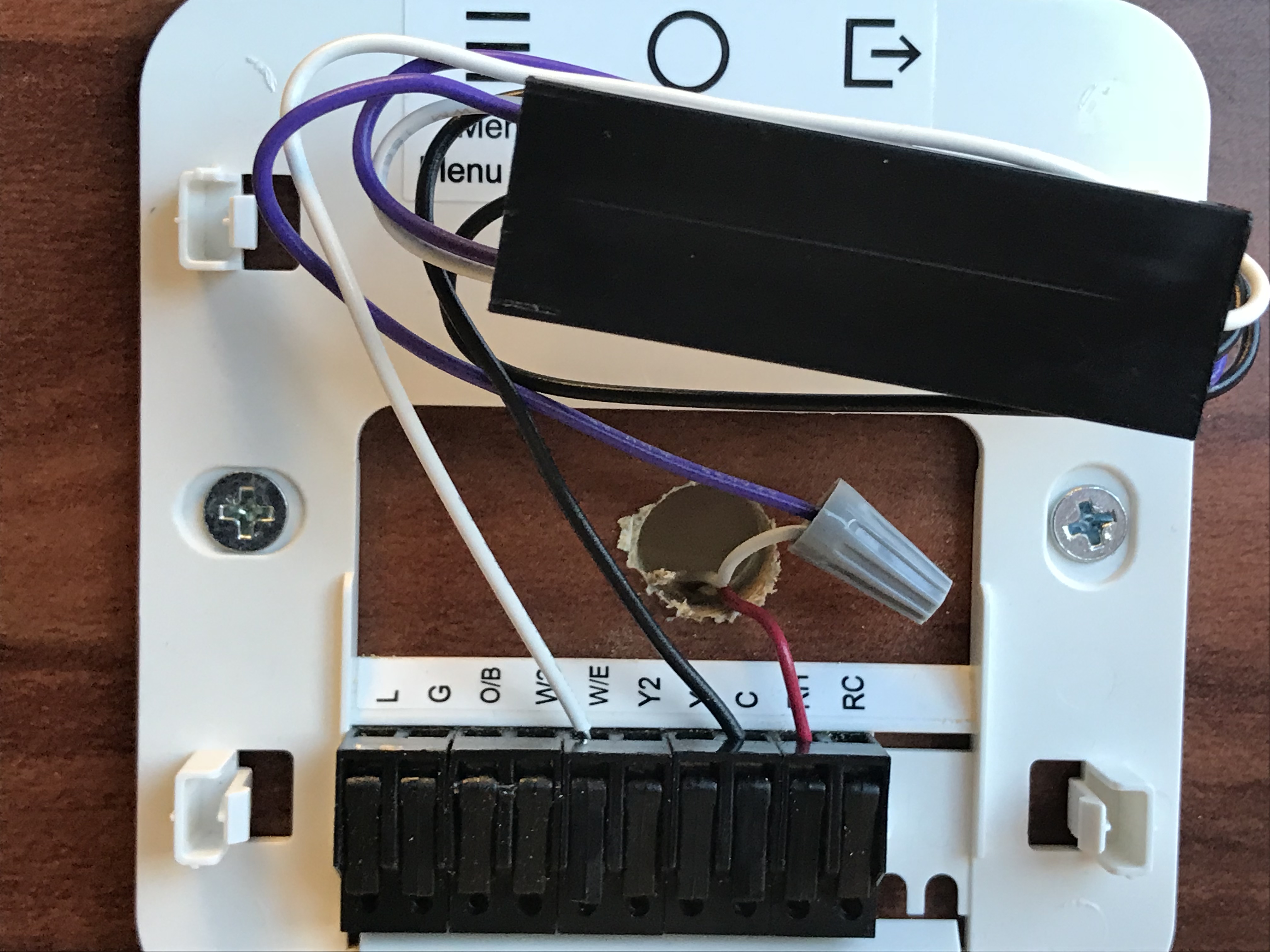
Disconnect the existing wires and remove your old thermostat wall plate. Hint: wrap the wires around a pencil to keep them from falling into the hole in the wall if needed. Install the Simple thermostat’s backing. You will now need to pull out the sender module from your Fast-Stat 1000 to continue with the installation, and follow the wiring guide below.
Now:
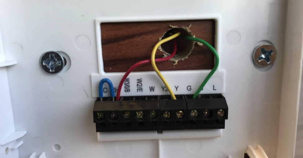
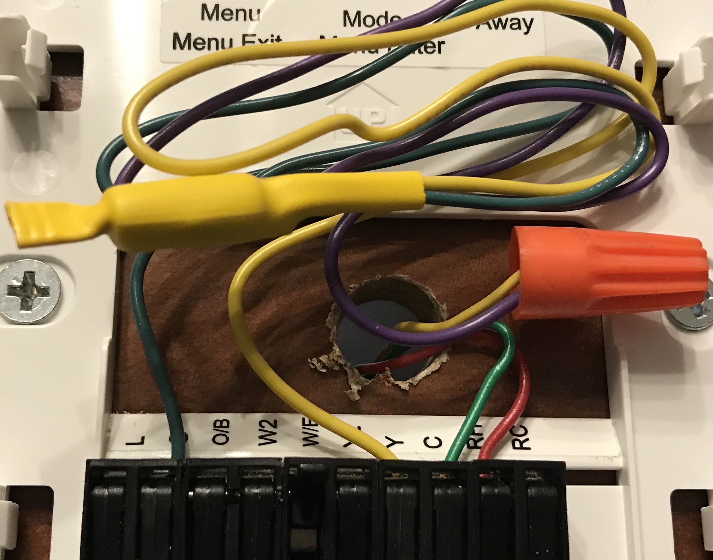
- Insert and secure your original Rh-wire and W-wire into their correspondingly labeled connectors on the Simple thermostat wall plate.
- Do not install the jumper wire between Rh and Rc; the Simple thermostat has an internal jumper.
- Take your original G-wire, and move it to the C position.
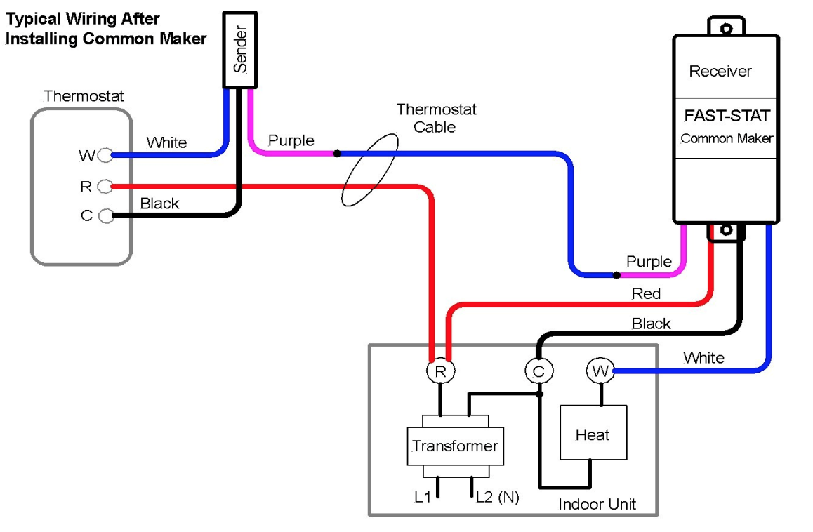
Following the wiring diagram from above:
- Insert and secure the sender module’s green wire into the G slot.
- Insert and secure the sender module’s yellow wire into the Y slot.
- Insert the sender module’s purple wire and your original Y-wire into a wire nut and twist until secure.
- Tuck the excess wiring, sender module, and wire nut into the wall to make room for the thermostat.
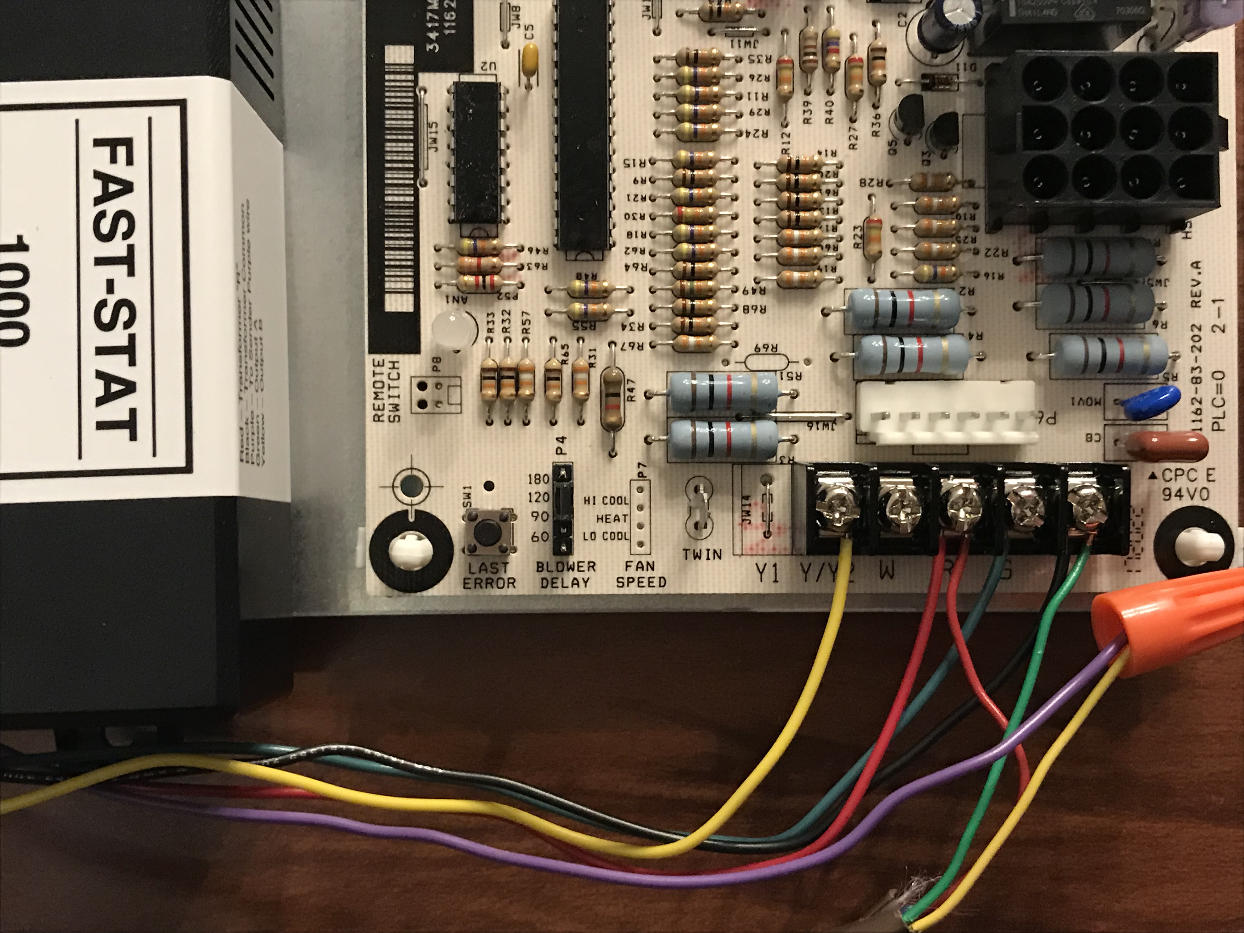
At the HVAC control panel:
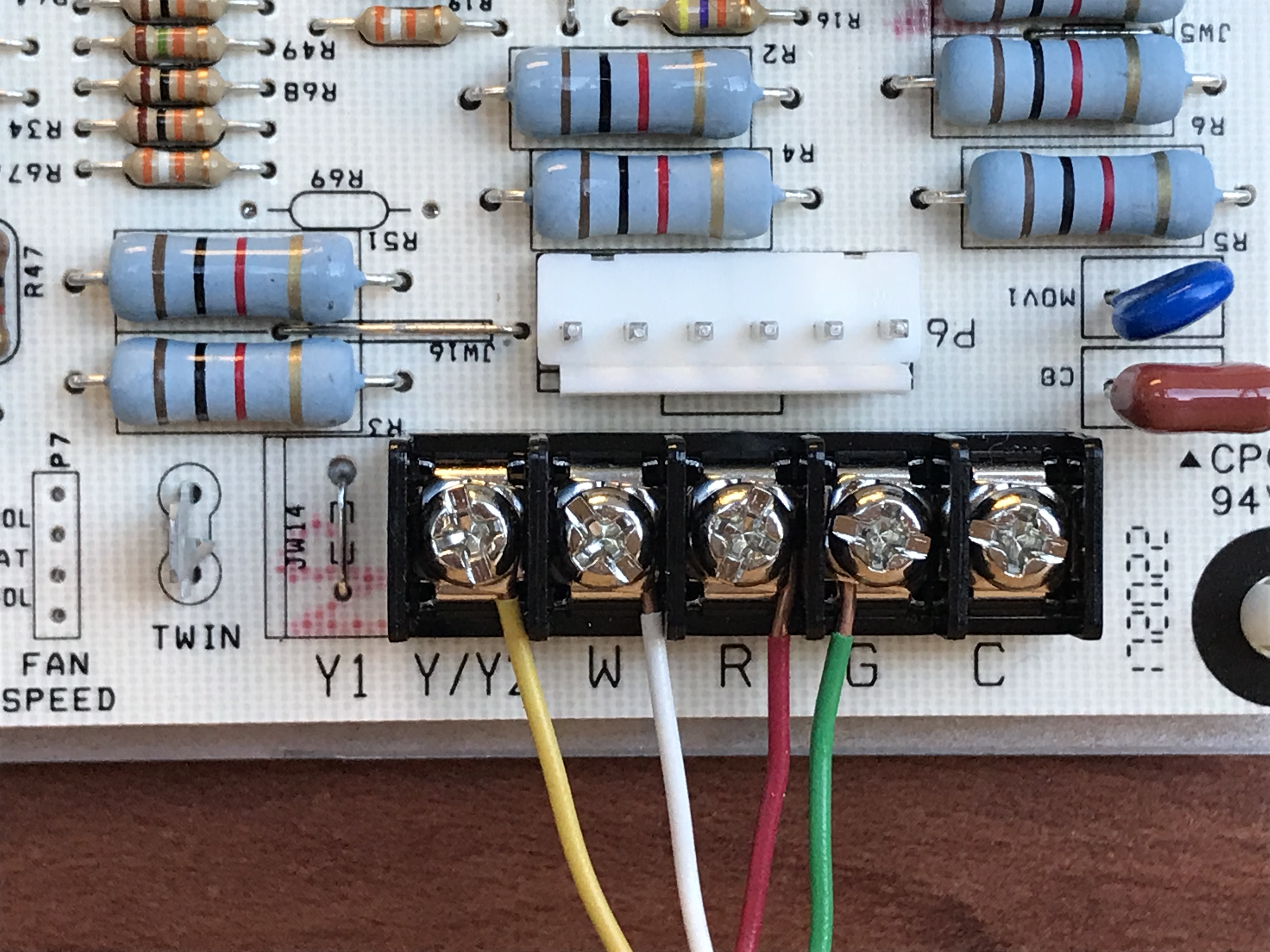
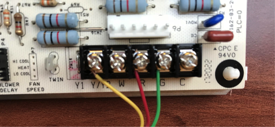
Moving to the system panel, you will have similar wiring. Take a picture of this wiring for reference as well.
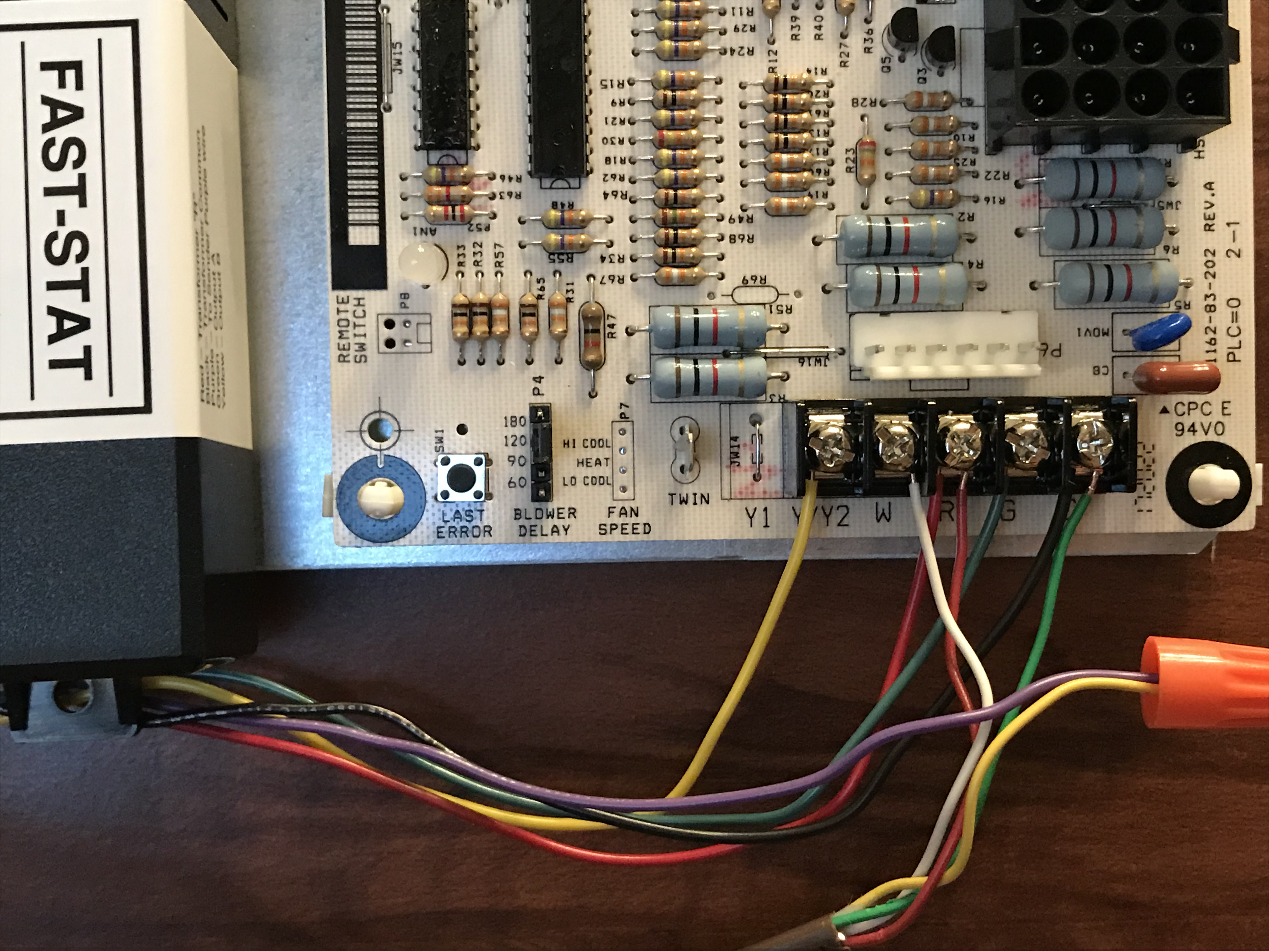
Retrieve the Fast-Stat 1000 receiver module
Now:
- Mount the receiver module to the system panel’s wall, near the control board.
- Following the wiring diagram from above, leave your R-wire and W-wire in place, and move your G-wire to the C terminal.
- Connect the receiver module’s yellow wire to the Y terminal.
- Connect the receiver module’s red wire to the R terminal.
- Connect the receiver module’s green wire to the G terminal.
- Connect the receiver module’s black wire to the C terminal.
- Insert the receiver module’s purple wire and your original Y-wire into a wire nut and twist until secure.
Once all wires are secured, close the control panel door, and turn the power to the system back on. You may now continue with your installation process.
3 Wire - A/C-only with Fan Control with the Fast-Stat 1000
At the thermostat:
Shut off the power to your thermostat and remove it from the wall. You should see a wiring setup that looks similar to the image below. Take a picture of this wiring to use as reference.
Disconnect the existing wires and remove your old thermostat wall plate. Hint: wrap the wires around a pencil to keep them from falling into the hole in the wall if needed. Install the Simple thermostat’s backing. You will now need to pull out the sender module from your Fast-Stat 1000 to continue with the installation, and follow the wiring guide below.
Now:
- Insert and secure your original Rh-wire into its correspondingly labeled connector on the Simple thermostat wall plate.
- Do not install the jumper wire between Rh and Rc; the Simple thermostat has an internal jumper.
- Take your original G-wire, and move it to the C-wire position.
Following the wiring diagram from above:
- Insert and secure the sender module’s green wire into the G slot.
- Insert and secure the sender module’s yellow wire into the Y slot.
- Insert the sender module’s purple wire and your original Y-wire into a wire nut and twist until secure.
- Tuck the excess wiring, sender module, and wire nut into the wall to make room for the thermostat.
At the HVAC control panel:
Moving to the system panel, you will have similar wiring. Take a picture of this wiring for reference as well.
Retrieve the Fast-Stat 1000 receiver module.
Now:
- Mount the receiver module to the system panel’s wall, near the control board.
- Following the wiring diagram from above, leave your R-wire in place, and move your G-wire to the C terminal.
- Connect the receiver module’s yellow wire to the Y terminal.
- Connect the receiver module’s red wire to the R terminal.
- Connect the receiver module’s green wire to the G terminal.
- Connect the receiver module’s black wire to the C terminal.
- Insert the receiver module’s purple wire and your original Y-wire into a wire nut and twist until secure.
Once all wires are secured, close the control panel door, and turn the power to the system back on. You may now continue with your installation process.
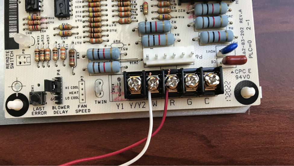
2 Wire - Heat-only with the Fast-Stat Common Maker
At the thermostat:
Shut off the power to your thermostat and remove it from the wall. You should see a wiring setup that looks similar to the image below. Take a picture of this wiring to use as reference.
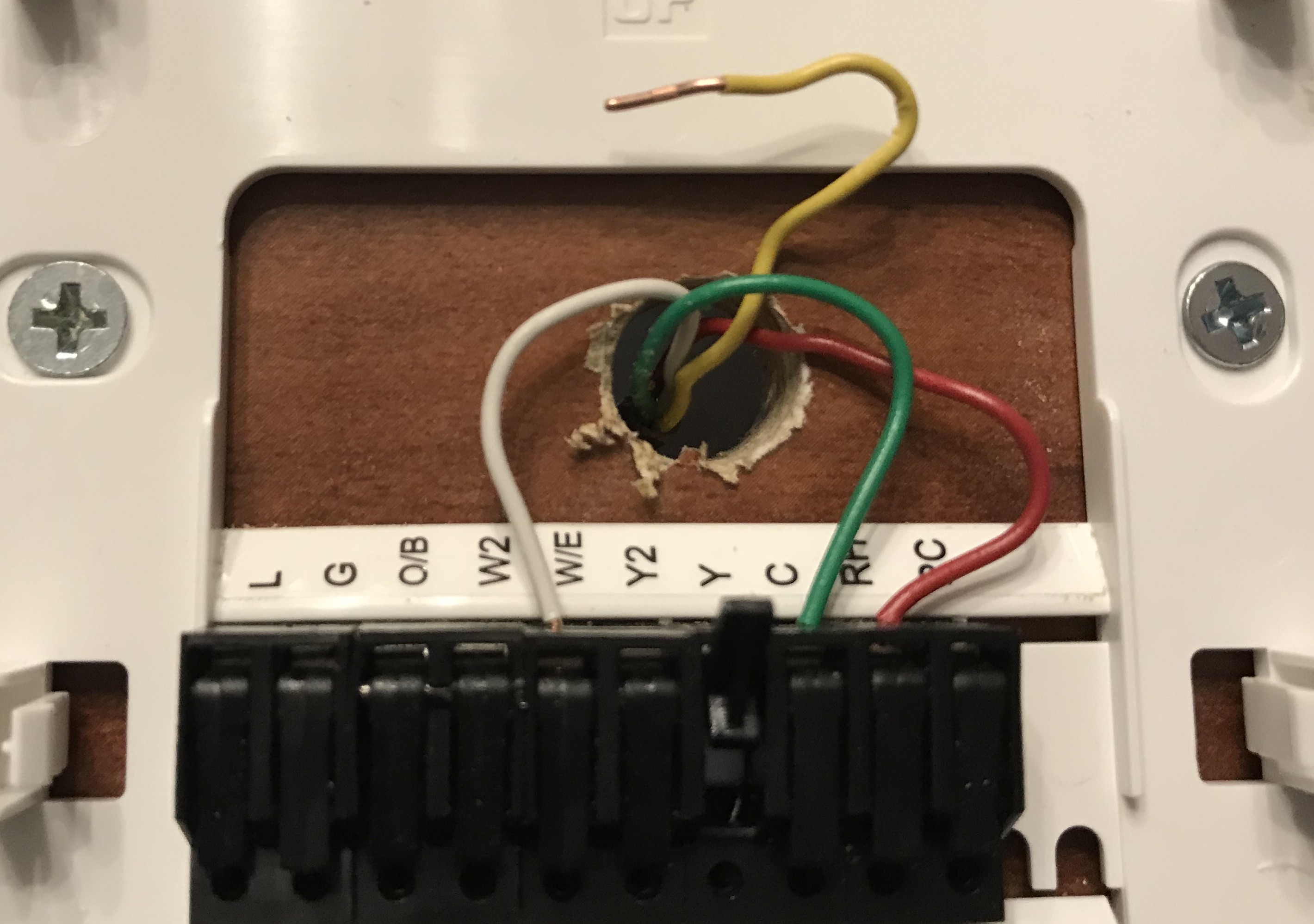
Disconnect the existing wires and remove your old thermostat wall plate. Hint: wrap the wires around a pencil to keep them from falling into the hole in the wall if needed. Install the Simple thermostat’s backing. You will now need to pull out the sender module from your Fast-Stat Common Maker to continue with the installation, and follow the wiring guide below.
Now:
- Insert and secure your original Rh-wire into its correspondingly labeled connector on the Simple thermostat wall plate.
- Do not install the jumper wire between Rh and Rc; the Simple thermostat has an internal jumper.
- Insert and secure the sender module’s white wire into the W/E slot.
- Insert and secure the sender module’s black wire into the C slot.
- Insert the sender module’s purple wire and your original W-wire into a wire nut and twist until secure.
- Tuck the excess wiring, sender module, and wire nut into the wall to make room for the thermostat.
At the HVAC control panel:
Moving to the system panel, you will have similar wiring. Take a picture of this wiring for reference as well.
Retrieve the Fast-Stat Common Maker receiver module
Now:
- Mount the receiver module to the system panel’s wall, near the control board.
- Following the wiring diagram from above, leave your R-wire in place, and disconnect your W-wire.
- Connect the receiver module’s white wire to the W terminal.
- Connect the receiver module’s red wire to the R terminal.
- Connect the receiver module’s black wire to the C terminal.
- Insert the receiver module’s purple wire and your original W-wire into a wire nut and twist until secure.
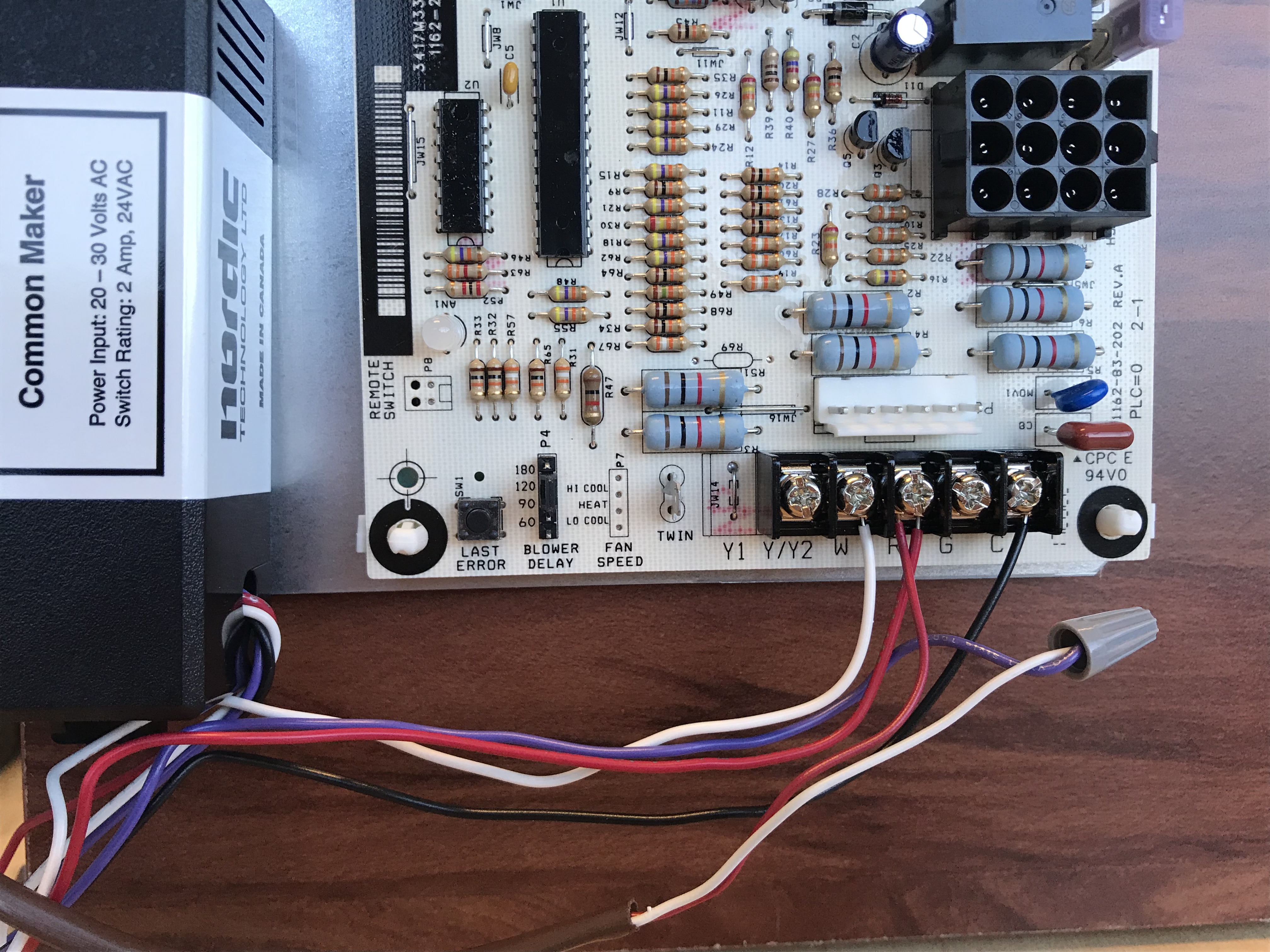
Once all wires are secured, close the control panel door, and turn the power to the system back on. You may now continue with your installation process.
Other Wiring Configurations
The Fast-Stat can be used in other ways for other wiring configurations to add one function to the system (e.g. you already have a common wire, but no manual fan control). The general operational considerations are:
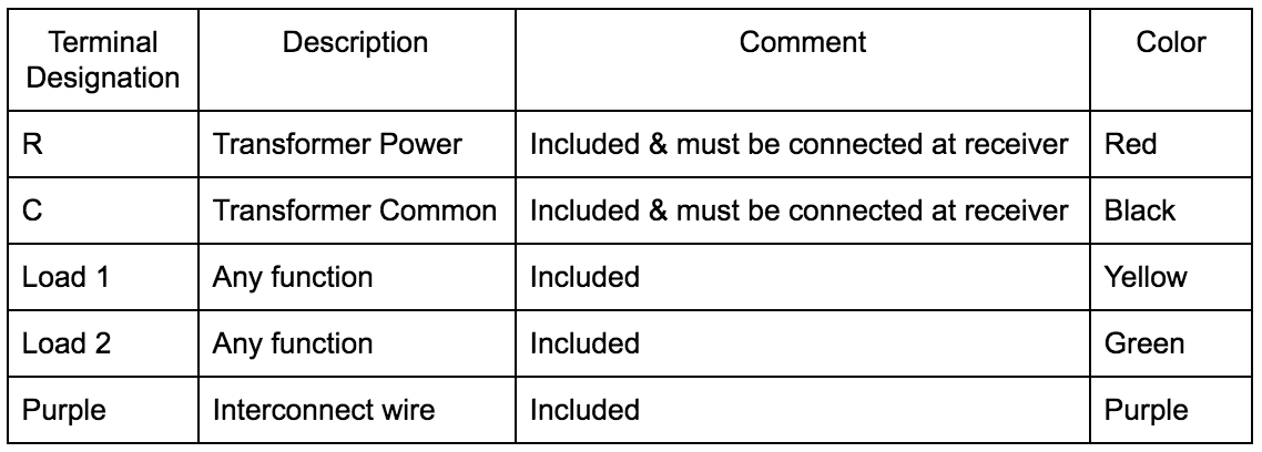
- The sending module's purple wire is connected to the receiver module's purple wire through the thermostat cable.
- An input on the sending module's green wire will cause an output on the receiver module's green wire. An input on the sending module's yellow wire will cause an output at the receiver module's yellow wire. Each channel is independent of each other.
- Transformer power "R" or "C" cannot be run through the sending unit.
- The receiver module's must be connected to a 24 volt power source through the module's red and black wires.
- The power supply must be between 18 to 30 volts. The total load must not exceed 2 amps.
Comments
0 comments
Article is closed for comments.